Microscopic Control
Make sure to follow the StellarScope Microscope System – Quick Start to assemble the microscope system and Zaber Stage before continuing with this section.
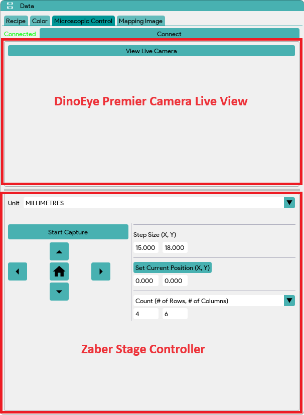
Zaber Stage Controller Information
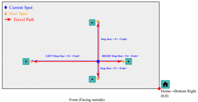
IMPORTANT NOTES: The Zaber Stage Controller controls the movement based on the probe’s perspective, although it is the stage that moves. Click the arrow in the direction you want the probe to move. For example, if you want the probe to point to the left, click the left arrow. The stage will move to the right as the probe adjusts its position.
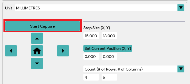
- Unit: The units to be used for setting the step size, current position, or sample size.
- Step Size (X, Y): Increment size when the controller buttons are clicked. X = left/right, Y = up/down.
- Set Current Position (X, Y): Input the desired X and Y positions in the input fields, then click Set Current Position to move the stage to that absolute spot. Note: (X, Y) = (0,0) is located at the bottom right corner of the stage.
- Home: Bring the Zaber stage back to the home position. The home position (0,0) is located at the bottom right corner of the stage.
- UP: Move up by <Y> <unit> as set in the Step Size (X, Y) fields.
- DOWN: Move down by <Y> <unit> as set in the Step Size (X, Y) fields.
- LEFT: Move left by <X> <unit> as set in the Step Size (X, Y) fields.
- RIGHT: Move right by <X> <unit> as set in the Step Size (X, Y) fields.
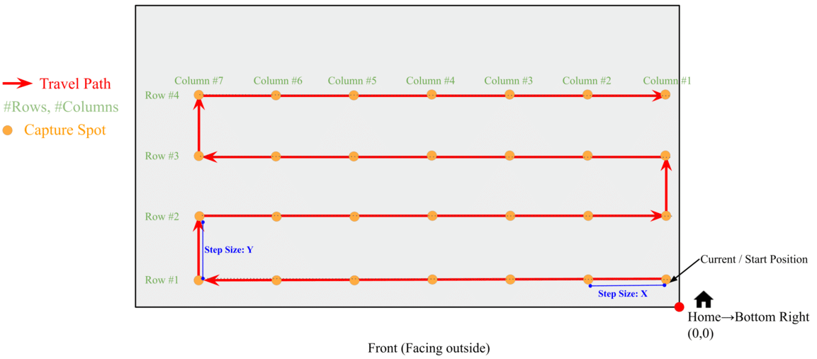
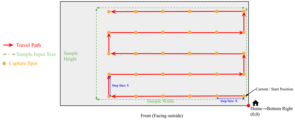
- Mapping Cycle Travel Options: The most optimized path will be used during the mapping cycle process. The process will first capture data to the left from the current/start position, then move up, then right, then up again, and then left. This sequence will repeat until the entire path is completed according to the selected mapping parameters, forming a rectangular path. Path visualization examples are displayed below.
-
- Count (# of Rows, # of Columns): Set the number of captures needed for each row and column starting from the current position. The distance between each capture is determined by the Step Size (X, Y) fields, where X represents the space between columns and Y represents the space between rows. The image below shows an example of a path with 4 rows and 7 columns.
-
- Sample Size (Width, Height): Traverse the entire sample based on the input sample width and height, starting from the current position and ending at the last position, according to the set step size. The spacing between positions is determined by the Step Size (X, Y) fields, where X specifies the width and Y specifies the height. Note: It is recommended that the sample width be divisible by the X step size and the sample height be divisible by the Y step size. Otherwise, a small portion at the left and top edges of the sample may be ignored if there isn’t enough space to complete another full step based on the set step size. Also, ensure that neither the start nor the ending position is at the edge of the sample to avoid invalid data capture.
-
-
- NOTE: If you have a circular sample, it is recommended to use a rectangular or square slice inscribed within the circular sample for the width and height, as shown in the example below. This approach helps avoid unnecessary captures that go outside the circle.
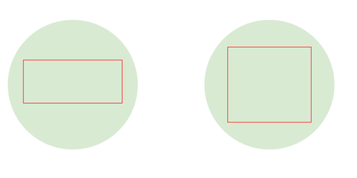
- NOTE: If you have a circular sample, it is recommended to use a rectangular or square slice inscribed within the circular sample for the width and height, as shown in the example below. This approach helps avoid unnecessary captures that go outside the circle.
-
- Start Capture: Begin the mapping cycle based on the input travel settings.
Film Thickness Zaber Stage Mapping Cycle
Note: Spectral View and Camera View cannot be used simultaneously. On the microscope, switch to Spectral View (switch to the left) to perform film thickness mapping cycle.
- Please follow the procedure in Performing a Measurement section to optimize the spectrometer and make sure the appropriate recipe is loaded based on the material of the sample.
- Ensure that the Zaber Stage power supply and USB are connected.
- In StellarPro-TFC, click on the “Microscopic Control” tab in the Data table.
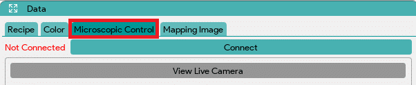
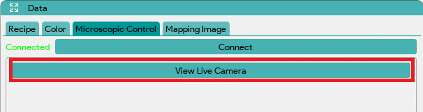
- In the “Microscopic Control” tab, click the “Connect” button if it has not been connected. If the Zaber Stage is detected, all buttons will be enabled; otherwise, ensure all power supplies and USB connections are correct.

- DinoEye digital camera: If wish to see the DinoEye digital camera, make sure that its USB is connected to the computer. Click the “View Live Camera” button to display live feed from the camera. You can click and drag the horizontal grey line under the window to adjust the live view window size. After adjusting the window size, click the “Stop Live Camera” button, then click the “View Live Camera” button again to see the adjusted window view. Note: Spectral View and Camera View cannot be used simultaneously. On the microscope, switch to Camera View (switch to the left) if you would like to use the camera. Ensure to switch back to Spectral View for the thickness mapping cycle.
- Place the sample on the Zaber Stage and use the Zaber Stage Motion Controller to align the first capture spot. This will be the initial spot where capturing will be performed when the Start Capture button is clicked. You may need to adjust the X and Y step sizes to increase or decrease each step. If you know the absolute position, enter the X and Y values under “Set Current Position (X, Y)” and then click the “Set Current Position (X, Y)” button to move to that exact spot.
- Once the first spot is located, select the travel options in the dropdown menu:
- Count (# of Rows, # of Columns):
- Input the number of rows and columns you wish to capture.
- Input the Step Size (X, Y) between the spots, where X is for columns and Y is for rows.
- Sample Size (Width, Height):
- Input the width and height of the sample you want to traverse, starting from the first spot to the last spot.
- Input the Step Size (X, Y) between the spots, where X is for width and Y is for height.
- Count (# of Rows, # of Columns):
- Once the travel settings are configured, click the “Start Capture” button to begin the mapping cycle. The stage movement will be updated in the current position fields after each move. You can abort the mapping cycle if you need to stop. However, if you abort while the cycle is in progress, you will lose all captured data.
- After the full mapping cycle is completed, the reflectance data for each capture will be automatically saved in the “Desktop > StellarPro-TFC Data > TFC” directory as a CSV file with a timestamp.
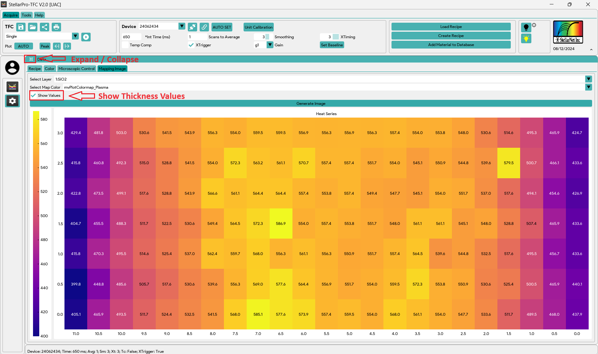
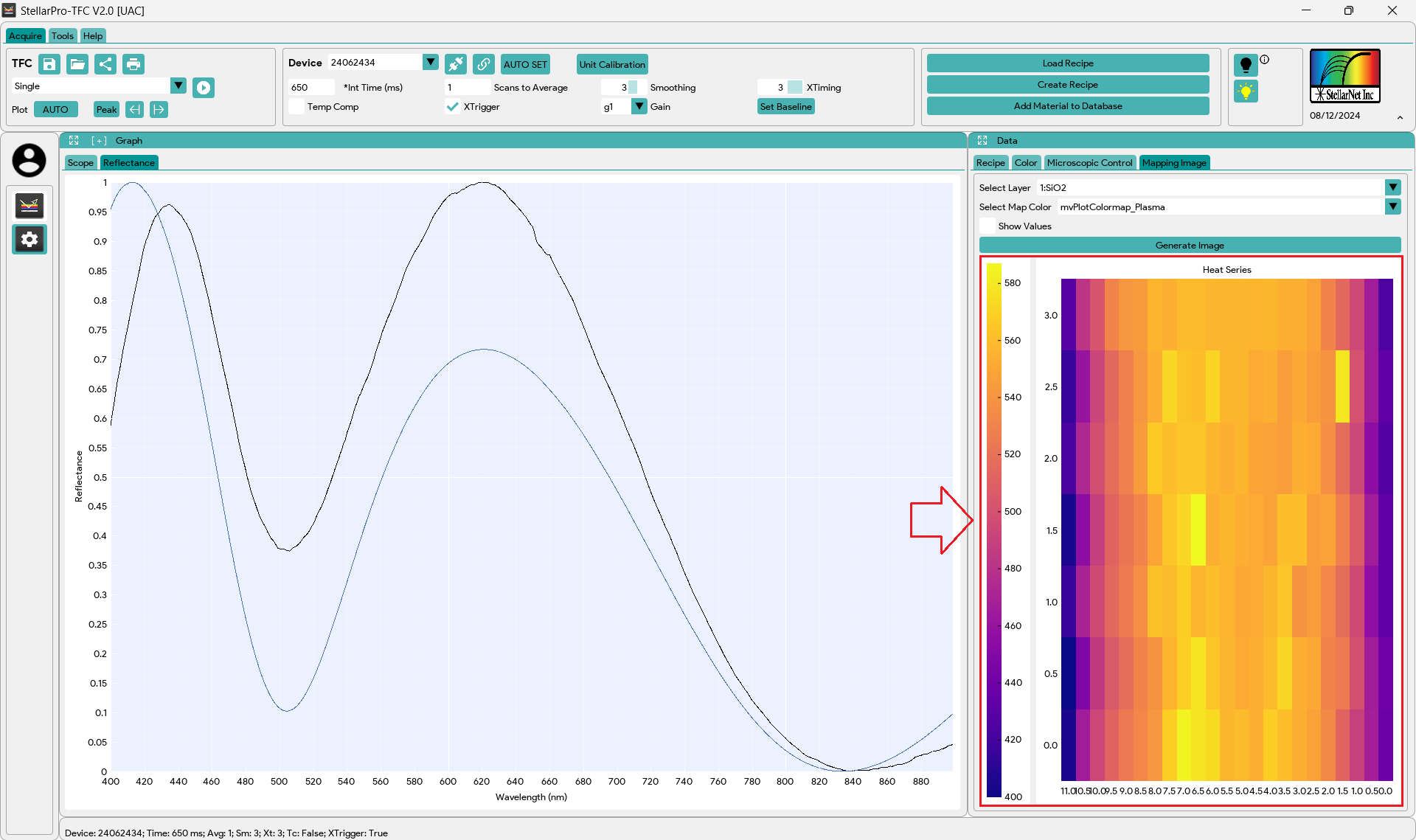
Generate Mapping Image
- Ensure that the full mapping cycle is completed. If you abort the capture before the mapping cycle is fully finished, the mapping image will not be generated correctly.
- Select the desired layer from the dropdown on which you want to generate the image.
- Choose the image color according to your preference.
- Click “Generate Image”. Depending on the data size, this process may take some time. Once the image is generated, it will displayed below. Note: The computed thickness data for all layers will also be automatically generated and saved in the “Desktop > StellarPro-TFC Data > TFC” directory as a CSV file with a timestamp.
- Additional Features:
- Expand / Collapse Data Window: Click the Expand / Collapse icon at the top left of the Data Window to maximize or minimize the panel.
- Show Thickness Values: Enable the “Show Values” checkbox if you want to see the thickness values on the image. Otherwise, leave the checkbox unchecked for an image-only view. Note: For a high-resolution image, it is recommended to turn off this option. The generated CSV file, stored in the “Desktop > StellarPro-TFC Data > TFC” directory, will provide better data visualization.